![]() Go to main contents page
Go to main contents page
![]() Special conditions for this system
Special conditions for this system
The customer provides the chilled water primary circuit upstream from the CLU.

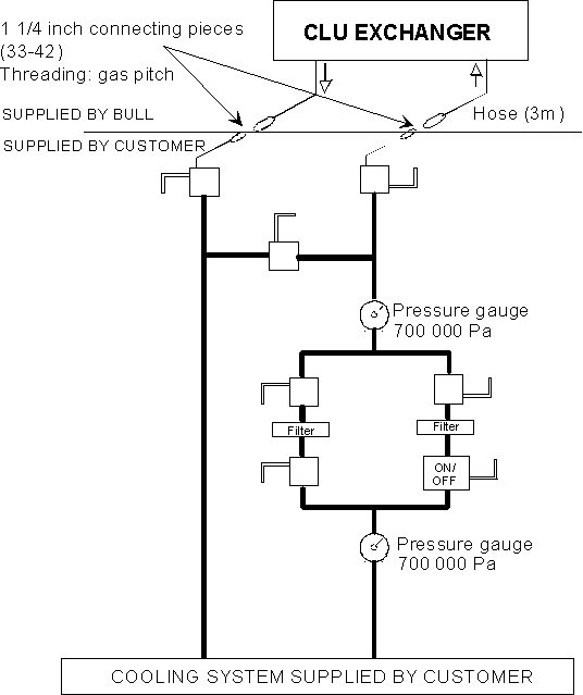
Customer-end chilled water primary circuit
Note: In the case of a two-processor system in tandem configuration, a second CLU is delivered. In this case, the installation shown above should be doubled up.
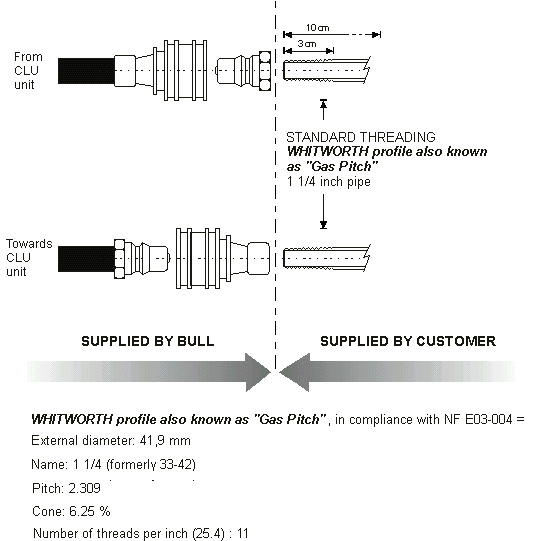
The connecting pieces of the connection pipes at the customer end should be 1 1/4 inch (33/42) in diameter and threaded so as to comply with gas pitch.The DPS 9000/8xx package delivered by Bull includes, together with the CLU, the connecting pieces for the 3-metre hoses which should be screwed onto the connecting pieces.

The customer is responsible for supplying the following items of equipment on the primary circuit:
Seven valves which should be installed in accordance with the figure entitled "Customer-end chilled water primary circuit" above.
Two stainless steel filters with removable strainers, to be placed on the by-pass circuits of this primary circuit, have a filtering diameter of 0.3 mm over a minimum length of 3 cm. These filters offer protection against foreign bodies and impurities.
Two pressure gauges designed to detect the clogging of these filters.
We recommend that provision be made for a thermometer, a flow meter and a pressure gauge at the level of the production of the chilled water so that you can monitor the values defined in this specification and according to the configuration of the DPS 9000/8xx.
The clips of the customer's chilled water inlet and return pipes should be assembled in a way which respects the fluid circulation direction (see figure "Clip assembly direction" above).
The cooling unit (CLU) is connected by 3-metre hoses fitted with quick-release flanged connections. As these connections are inserted horizontally, sufficient room must be left to connect and disconnect them.